In this blog, we will see how we can build a simple content-based recommender system using Goodreads.com data.
Originally from KDnuggets https://ift.tt/3jR7vHU

365 Data Science is an online educational career website that offers the incredible opportunity to find your way into the data science world no matter your previous knowledge and experience.
Originally from KDnuggets https://ift.tt/3jR7vHU

Hi there,
Recently, Rul.AI hosted their first online Conversational AI certification course, and sold out in less than 10 days. They handed out 53 Accredible certifications at the end of the 2 week class.
Conversational AI skills have never been more in demand. So, we’re pleased to announce our next Conversational AI certification course, with separate tracks for developers and designers.
Now is a perfect time to build up your Conversational AI capabilities and skills on the world’s most advanced chatbot platform. Rulai Institute’s certification courses are entirely online, and 100% free.

August 17–28: Rulai Institute’s popular online Conversational AI certification course (with separate designer and developer tracks). Now open for sign-up.
Each track includes 3–4 hours of live instruction per day, combined with hands-on practice and on-demand 1:1 guidance. Designers will focus on the study of conversational design principles where as developers will get an in-depth understanding of Rulai’s system architecture, integration capabilities, omni-channel support, as well as API and analytics tools.
Space is limited. Sign up today to reserve your spot and earn a Conversational AI certificate upon successful completion of the course.
Have a great day,
Stefan
FREE: NLP & NLU Training with RUL.AI was originally published in Becoming Human: Artificial Intelligence Magazine on Medium, where people are continuing the conversation by highlighting and responding to this story.
Via https://becominghuman.ai/free-nlp-nlu-training-with-rul-ai-1b4d90d85633?source=rss—-5e5bef33608a—4
source https://365datascience.weebly.com/the-best-data-science-blog-2020/free-nlp-nlu-training-with-rulai
Originally from KDnuggets https://ift.tt/30SnIDH

A telltale story of how I created an Altium Database library for our company with the help of Python programming.
How it started
Recently I had started a couple of small projects in our company. And while I was designing schematic and PCBs in Altium, there was a thing that was bothering me. As in most of the projects, most of the components in my projects were getting reused from our existing design. However, in order to use those components, I was having to recall which projects might have used the part which I was needing for my project, open its Altium project, copy the schematic symbol and footprint for the component from existing project’s library files, copy them in my new project’s library file and finally link newly pasted schematic symbol to PCB footprint. This in itself was annoying, but there were couple more things which were bothering me.
For cookie-cutter parts like SMD resistor and capacitors, we would be using a generic schematic symbol in schematic and assign one of the standard footprints we had created for them and then update value and company and manufacturer part number details. This was also time-consuming and error-prone as sometimes I would miss updating some of the details.
And thirdly, while in the middle of my new projects, we found out that one of the footprints we were using for an existing project was a little incorrect. It was for an oscillator component and there was a chance that one of the alternate parts we were using would not fit into our footprint. For this, I basically had to do the reverse process of what I had described earlier. I had created a new footprint for my project and had to update the existing project’s PCB library.
All these things finally lead me to start exploring about creating a centralized library for all EEs in our company. Incidentally, at the same time, I came across a presentation from Robert Feranec at Altium live (you can watch it here) in which he presented his survey about how libraries are maintained in different organizations. While there are lots of interesting things presented in the speech, the one thing which stood out to me was, as per Robert’s study, in almost all the companies it was always an initiative by one or two individual engineers which has led to the creation of centralized libraries. Someone starts by creating a library, presents it to the group and once the group and management see that it’s already in motion, then everyone starts using and contributing to it. And I knew it then and there itself that this is what was required for our company too. Something to get started with and then it will pick up the pace by itself. And hence, I decided to start creating an Altium component library for all the Electronic parts which were used by our company.
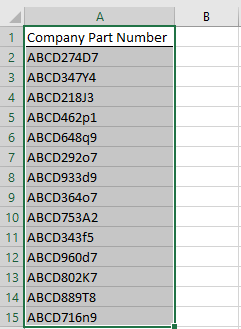
Step 1: Get all Company level part numbers
Most of the companies have their own part number system where the same parts (drop-in replacement to each other) are given just one company level part number. E.g. all 0402 1KOhms 0.1W, 5% resistor will have the same xxx company part number. Luckily for me, our company had an excel file containing all the company level part numbers that are used by engineering, and that was all I needed to get started.
Result: Got all company level part numbers in an excel file.
Step 2: Get actual vendor details from company part numbers.
Our company uses an Oracle system to store all documentation. My next challenge was to get the actual manufacturer name and part numbers from our Oracle system for every part. This is where I started using Python. I specifically used pyautogui and openpyxl libraries. I didn’t automate from A to Z, as this was just for my one-time personal use and it was easier to click one button to open the tool once rather than write 10 lines of Python code. So, I opened our Oracle tool and ran a few lines of codes that will automate mouse movement and clicks. Unfortunately, as I couldn’t show you screenshots of our tool, I created a small gif using powerpoint to show the steps involved in getting vendor details from the tool.

Steps shown in the above gif can be coded in python with the help of pyautogui as will be explained below. But before we start to code, there is one thing which we need to know, and that is how to find the location of a particular element, like a button (Find Vendor details, Search and Close), text box, etc. on our PC screen. We can do that by just using a single line of code available in pyautogui, which is pyautogui.position(). Just place your mouse pointer on top of the button or text box whose location you want to find and run pyautogui.position() in your python terminal. For more information on how to use pyautogui, refer to their documentation here.
1. Natural Language Generation:
The Commercial State of the Art in 2020
4. Becoming a Data Scientist, Data Analyst, Financial Analyst and Research Analyst
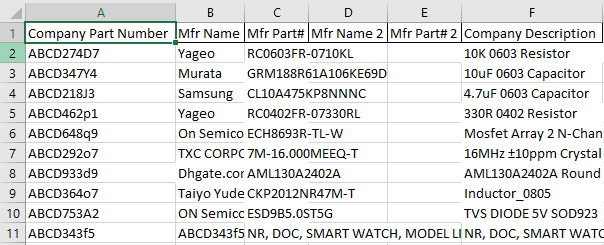
And there I had it, an excel file with all company part numbers with corresponding vendor details. Well, as you could have imagined, not all parts had valid vendor details, and many of the parts were actually just internal documents or some mechanical components. As with any data engineering kind of job, I had to do clean up the data as we will see below.
Result: I had a file with the manufacturer name and part number updated against company part numbers.
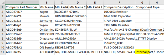
Step 3: Remove internal document parts
Part numbers which were our internal documents (like row# 11 in the above screenshot) had our company’s part number itself in ‘Mfr Name’ field mentioned in the above step. So it was easy to filter them out. I just search for parts that had our company part number itself in vendor name and marked it with “Internal part / Document.” I used a script similar to that given below to get this result.
Result: Internal parts / Documents identified.
Step 4: Identify the component type.
I wanted to organize our database according to the type of components. This would allow engineers to search for a component from the database using its type and value. So as the first step for that, I had to go through each vendor part number, search for the component in Digikey and mark its type. In order to use a web browser (and Digikey website), we will be using webdriver module from selenium library in Python. You can learn more about this library here
The most important part in order to surf through a website using selenium is to find the ‘path’ of the element (again, like button, text box, etc.) on a webpage. It’s very much similar to how we had to find x, y location of button, etc. in the above section. There are multiple ways to find location/path of an element, one among them is to use something called ‘XPath’.
You can see the process of using XPath to find an element on a webpage in below couple of gifs.


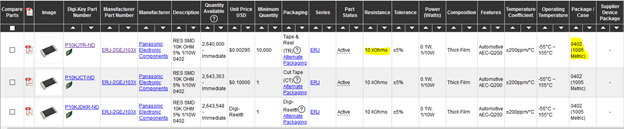
Coming to the coding part, first I go to Digikey, search for the ‘search’ bar using it’s XPath, paste the manufacturer part number from my Company_Database excel file, and press enter. After waiting for a couple of seconds to allow the page to load, I would extract the type of component from the following field in the Digikey page. While looking for the best way to find the type of component, I had decided it would be best for me to use the classification used by Digikey itself, rather than me trying to decipher it from the part description. After a few long stares at Digikey pages for various components, I observed that Digikey will identify a component in the hierarchy of three levels. The Below picture shows how a Capacitor, Resistor, Crystal, and a Diode will be categorized in Digikey.

Once I saw this, then it was easy, I again ran through all parts (this time excluding parts marked as “Internal parts / Documents” and copied the third entry in the above-shown product categorization.
Result: All components now have a ‘Component Type’ associated with them.

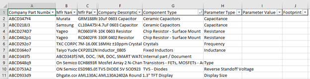
Step 5: Get one Key parameter for each component.
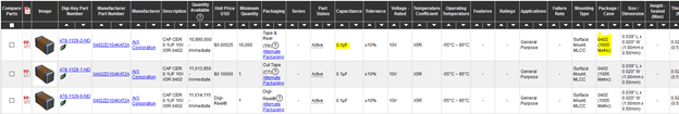
After identifying the type of components, I wanted to know it’s principle value, like resistance for a resistor, capacitance for a capacitor, oscillating freq for the crystal, and so on and so forth. Again, this was an exercise in going through a few parts of each type and finding where can I find the value of its key parameter along with the footprint. Key-value and Footprint were the two parameters that I wanted to include in the database library to help to sort out the components. I first of all sorted the Company_Database excel file with “Component Type”, then manually decided which parameter I want to use for each type of component.
Once I knew which parameter I want to get from Digikey for every type of component, I wrote the function shown below to get the respective value and Footprint for the components. As you can see in the below function, first we check what type of component it is. And then depending on the type of component, I take values from two of its parameters from Digikey using their XPath. Below are a couple of screenshots that show examples of where to get the value and footprint for Resistor and Capacitor type of components.
With this, the majority of electronics components in our database got sorted out according to their type, value, and footprint. Whatever little were reaming, I updated their values and footprint manually. These components were one-off types like Buzzer, Cable Ferrite, displays, and so on.
Result: All valid part numbers have a type, value, and a footprint associated with it.


Step 6: Components Not Found in Digikey.
After the above step, there were few components for which its type, and hence its value and footprint could not be obtained from the script. This was happening because of the following three scenarios.
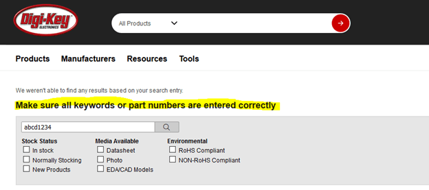
a) Component not found in Digkey. In this case, it was obvious for it to be not categorized.
b) In some cases, there was an exact manufacturer part number provided in our database and hence Digikey will directly take me to a single product page like this. As the location (XPath) of component’s type, value and footprint will be different in this kind of page than the ones shown in above steps, the script was not able to identify components which had a complete part number.

c) Partial part number components, for which Digikey had multiple types of products with a same part number like shown below.

Take note that categories ‘a’ and ‘c’ are different. In ‘a’ Digikey is sure that it doesn’t have any part matching our part number, whereas in ‘c’ it could find multiple options. As there were a relatively lesser number of components left combined in ‘a’, ‘b’, and ‘c’ categories, I decided to update details for them manually. For ‘a’ and ‘c’, the script would have been too much complicated for the scope of this project. And for ‘b’, there were just not enough components left. Even if there were 10 components of the same type with scenario ‘b’, I would have started writing function similar to the one in step 5. The only difference in this new function would be the XPath of the element from where I would be getting component details.
Step 7: Company_Database Excel File Structure
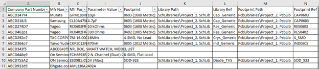
Before I get into the next section of getting Schematic Symbol and Footprint details for components from existing Altium projects. I would like to show all the columns I planned to have in the Company_Database excel file. These are slightly bit different from the example screenshot I have been sharing with you before. E.g. in my actual Company_Database excel file, I have columns for second manufacturer details along with Column G for ‘Owner’ of the part. I had derived this additional info from our internal repository tool.
They are not arranged in the best order, as I have seen that when I import this excel file in Altium, the columns would get rearranged and I would anyways need to arrange them in Altium. The second reason for why my columns were in such an order was because of the sequence in which I was populating this file. In step# 1 when I first got all company part numbers, they obviously got populated in Column A. In step# 2 where we got manufacture details from the internal database system, I was retrieving them in the order of categories entered in Column B to H.
Column A — Company Part Number
Column B — Manufacturer Name
Column C — Manufacturer Part Number
Column D — Manufacturer 2 Name
Column E — Manufacturer 2 Part Number
Column F — Company Description
Column G — Owner (Engineer who had created this company part number)
Column H — Date (G & H were coming from internal database system. Thought no harm in having them)
Column I — Project (Will be updated in later steps)
Column J — Component Type (As updated by script in step 4)
Column K — Parameter Type (As updated by script in step 5)
Column L — Parameter Value (As updated by script in step 5)
Column M — Footprint (As updated by script in step 5)
Column N — Library Path (Altium Schematic Library path)
Column O — Library Ref (Altium Schematic Symbol Name)
Column P — Footprint Path (Altium Footprint Library path)
Column Q — Footprint Ref (Altium Footprint name)
Column R — Footprint Path 2 (Altium Footprint Library path if multiple footprint are available)
Column S — Footprint Ref 2 (Altium Footprint Name if multiple footprint are available)
Column T — Datasheet# 1 Link (Link to additional information like datasheet or app note)
Column U — Datasheet# 2 Link (Link to additional information like datasheet or app note)
Column V — Signal Integrity (For future use)
Column W — Simulation (For future use)
Column X — Created by (Engineer who created this Altium part)
Step 8: Get footprints from existing Altium Projects.
First, we were working on an internal repository tool, then with the Digikey website and now finally we get our hands on Altium Designer. After getting manufacturer details for all electrical parts used in our company, it was time to get Altium footprint for the components from the few projects we have already completed since we changed to Altium. As I said in the opening sections, right now in our Altium projects, we are using all sorts of libraries, like those created by individual engineers, or an integrated library, or library borrowed from other projects. To make the problem of getting a Schematic symbol and PCB footprint easier, I generated one Schematic and PCB library for each project. By doing this it would get easier for me to get a schematic symbol and footprint for each component. Instead of trying to find it from different libraries, I would have to search for it in only one project library.
Creating Schematic and Footprint libraries from the project is very easy in Altium. Just open up your Altium project — Open schematic page — go to the Design tab — Click on Make Schematic Library.
Similarly for PCB library, open PCB file — Go in Design — Click on “Make PCB Library”.

After creating libraries, I generated BOM from Altium projects having the following fields — Company Part Number, LibRef (gives me names of the schematic symbol), and Footprint (gives me footprint name for Column Q).
Step 8: Remove Duplicate Part Numbers from Project BoMs
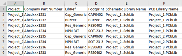
After getting BoM for each project, I vertically stacked them together as shown in the below example screenshot. I also added a couple of columns manually to each BoM having the name of the Schematic and Footprint library which I generated for each project in the above step. After stacking them together, I used Excel’s ‘Conditional Formatting’ tab to highlight duplicate parts to identify multiple instances of the same Company Part, and deleted them.
Result: Now I have a clean list of parts, organized by Company Part Numbers, for which I have Altium Schematic symbol and Footprints.
I arranged my database folder as shown below. It had a simple folder structure. The reason for this is because while creating our Altium Database library, we need to provide the location address of the Schematic symbol and Footprint for each part. You will get more clear about it when we populate Columns N to S in our Company_Database excel file.
Database Folder
— (Folder) PcbLibraries
““““— (Altium PCB Library) Project_1.PcbLib
““““— (Altium PCB Library) Project_2.PcbLib
““““— (Altium PCB Library) Project_3.PcbLib
— (Folder) SchLibraries
““““— (Altium Schematic Library) Project_1.SchLib
““““— (Altium Schematic Library) Project_2.SchLib
““““— (Altium Schematic Library) Project_3.SchLib
— (Altium Datbase Library File) Company_Database
— (Ms Excel 97–2003 Worksheet) Company_Database
With a list of Altium parts created in step# 8, I wrote a simple function to execute the following steps.
a. Take Company Part Number form Altium Parts List.
b. Search for that part in the Company_Database excel file.
c. Update column I with column A from the Altium Parts List file for matched parts in the Company_Database excel file.
d. Update Columns O and Q by columns C and D from Altium Parts List — Name of Schematic Symbol and PCB Footprint respectively.
e. Update Column N with “SchLibraries\” + Column E from Altium Parts List. E.g. for parts matched from project 1, Column N in Company_Database will be updated as SchLibraries\ Project_1. SchLib. This will provide the complete address of the library where the Schematic symbol for this part is kept.
f. Update Column P with “PcbLibraries\” + Column F from Altium Parts List. E.g. for parts matched from project 2, Column P in Company_Database will be updated as PcbLibraries\ Project_2. PcbLib. This will provide the complete address of the library where the PCB Footprint for this part is kept
g. Update Column X with the name of the project from Column A of Altium Parts List.
Columns N & O and Columns P & Q provide Altium with complete address of the Schematic symbol and footprint for each component. We will see how we tell Altium that these are the columns from where it should take the addresses and names of symbol and footprint respectively in a later step.
But once we do that, columns N and P will provide Altium with a complete path to the library of the part. As you can see, this is a relative address with respect to the location where the Altium database library itself is stored. For e.g. on seeing SchLibraries\ Project_1. SchLib and PcbLibraries\ Project_1. PcbLib in Columns N and P, Altium will traverse through folders SchLibraries and PcbLibraries and access Project_1. SchLib and Project_1. PcbLib respectively. After that, it will use Columns O and Q to search for actual Schematic Symbol and corresponding Footprint for the part.
Result: In this step, we took our Altium parts list from step# 8 and updated Company_Database excel file with Schematic Symbol and Footprint details for the parts contained in Altium parts list.
Step 10: Update Schematic Symbol and Footprint for gelly bean parts
As you could imagine, in our Company_database excel file, there are tons of parts like Resistor, Capacitor, and Inductors in standard packages like 0402, 0603, 0805 respectively. These packages are standard throughout the industry and there is little risk in copying schematic symbols and footprints from one part with the same package to another. And that’s what we are going to do next. There is no need to write any function for this as this can be easily done in excel itself. In the Company_database file, I filtered Column J (Column G in screenshot examples), for e.g. to only show “Ceramic Capacitors”. Then sort Column M (Column J in screenshot examples) in the “A to Z” order. This will group all parts with the same package together. Now I just took the part which had Altium schematic symbol and footprint available, copied its Columns N to X, and pasted them in corresponding columns of the parts with the same package.
Repeat this for all components and packages you feel are compatible, like Resistors in 0402, 0603 and 0805 packages etc. and you are done with creating database file for your parts.
Pat yourself on the back ? as most of the hard work is done and now we just need to set up this newly created Company_database file as Altium library.
Step 11: Create Altium Database library
Create a new Altium database file by going to File » New » Library » Database Library from the main menu. On getting below dialog box, select “Microsoft Excel” in the dropdown box and select your “Company_database” excel file.
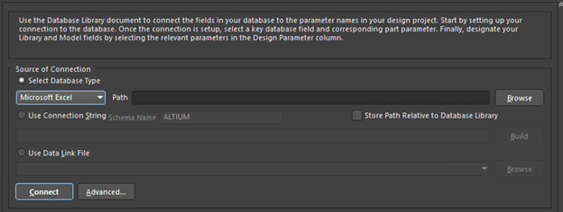
If your MS-Office / Office 365 is a 32-bit version, you may get an error. Refer to this link to work around it. You can use “Advanced PCB Library Management” article from Altium to know more about using the Database library in Altium.
With that, it’s a wrap. Hope you liked the article and can use it to make yours and your fellow EEs life easier by creating component library yourself for your company. Feel free to drop me a message in case you got any questions, suggestions, concerns …or even just to say Hi.
Till next time….cheers!!!! ?


Use Python to create Altium Database Library was originally published in Becoming Human: Artificial Intelligence Magazine on Medium, where people are continuing the conversation by highlighting and responding to this story.
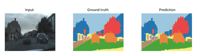
When learning image segmentation UNet serves as one of the basic models for the segmentation. UNet is one of the most used models for image segmentation. You can see people are making a lot of changes in the Original UNet architecture like using Resnet etc. but let’s implement the Original UNet Architecture. in 7 Steps
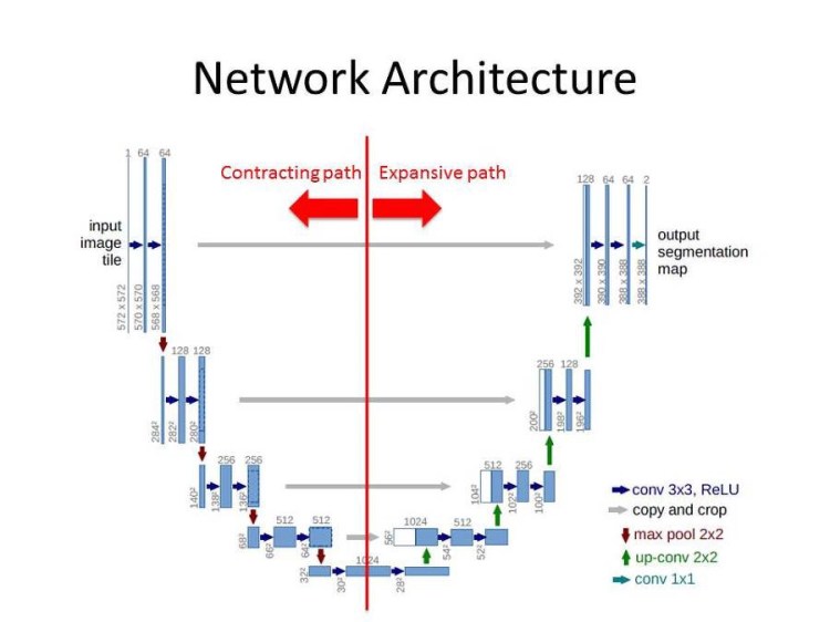
The architecture of the Unet can be divided into two part Left (Contracting path) & Right (Expansion path).
The Left part is just a simple convolution network. In the left part Two 3×3 Convolution layers followed by a Relu activation function are stacked together (Sequentially) and a 2×2 maxpool layer is applied after that(red arrow in image) First vertical bar in the left side in the image is not a layer but represents the input.(input image tile)
The Right part is where interesting things happen. Right part also uses Two 3×3 Convolution layers stacked together (Sequentially) like left side but no Relu activation function is used and there is no maxpool layer used instead a 2×2 Transpose convolution layer is used (green arrow in image ). During the expansion path, we will take the image (copy ) from the left side and combine it with the image on the right (grey arrow in the image). Remember a sequential 3×3 convolution layers are also used in the right side so the input for that will be combination of the image from right and its previous layer (half white and blue box in the right side of the image is the combination).
The output layer on the right side an extra convolution layer is applied (output segmentation map ).
So let’s just code the Unet architecture.
Full code : Github
1. Natural Language Generation:
The Commercial State of the Art in 2020
4. Becoming a Data Scientist, Data Analyst, Financial Analyst and Research Analyst
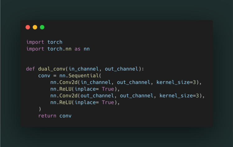
As we have seen in the architecture a 3×3 double convolution layer followed by the Relu activation function is used on both right and left side.
Step 1.
a dual_conv() function is created with the in & out channel parameters.
inside the function, a Sequential layer of two convolution layers with kernel size 3 (3x3 conv) each followed by a relu activation is made.
dual_conv() returns the conv a sequential layer
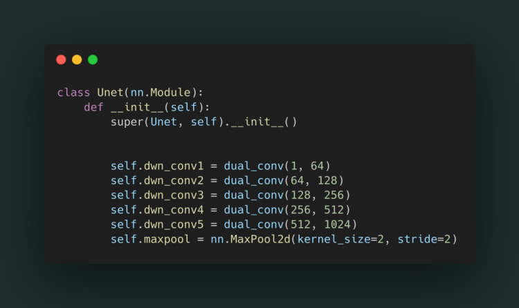
Step 2.
We will create a class Unet() and make the layers of the left side and a maxpool layer(the red arrow in image). In each layer, we use dual_conv() as it uses dual convolution. Let's just name the layer as dwn_conv (5 layers are on the left side).
Step 3.
Make a forward() function inside the class in which we will forward pass the input(image) to the left side layers
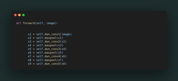
WALAAHH… left side is complete
After passing the image from left side the interesting part came Right side of the architecture.So let’s just implement that.
Step 4.
Now let’s declare the 4 layers of the right side in the __init__() function of the class and the last 1×1 conv. output layer. 2×2 transpose convolution is used instead of maxpool as in the left side

Step 5.
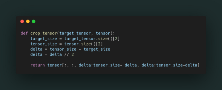
As we seen in the architecture the input image on the right side is combination of the image from left side (grey arrow in image) and its previous layer. But for combining the imaged it has to be the same size images so lets make a function out side the class to crop the image.
what happens in crop_tensor() images = tensor
tensor = image from the left side which needs to be cropped
target_tensor = image on the right side  whose size has to be matched by cropping left side image
take the size of both the tensors in target_size and tensor_size .
[2] takes only last value of tensor width , as height and width are same  eg:torch.Size([1, 512, 64, 64]) so it take [2] = 64
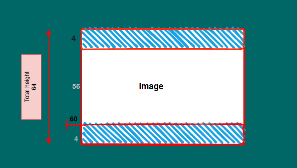
now we got the size of both the images we will subtract the size of lower tensor'target_size' from bigger one 'ternsor_size' .Suppose target_size=56 and tensor_size=64 so delta(subtracted size) will be 8
but we will crop image from all corners 'height' * 'width' so we will divide the delta by 2   so that height and width can be cropped equally
 8 =>h*W = 4*4

now return the cropped tensor
[:, :,] = all dimensions
[delta:tensor_size-delta, delta:tensor_size-delta] = cropped image
[4:64-4, 4:64-4] => 4:60, 4:60 in above example we need 56x56 img
see the below image height as an example
Step 6.
Forward pass on the right side we will make this in the forward() function inside the class
first is transpose layer x takes input x9 the last layer of left side.
now combine the images of x  and layer in front of it(left side), but wait the size of two images are different so we will crop the image using crop_tensor() function, size of x is smaller then x7
print(x7.size())  :torch.Size([1, 512, 64, 64])
print(x.size())  :torch.Size([1, 512, 56, 56])
combine both the images using torch.cat() and pass it to up_conv()

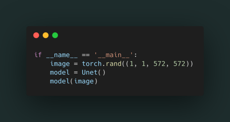
Step 7.
Lets just make a image (as image is just a tensor ) by using torch.rand()
572 x572 image height x width as Unet take 572×572 image as input
and pass it to the model.
Full code : Github
Implementing UNet in Pytorch was originally published in Becoming Human: Artificial Intelligence Magazine on Medium, where people are continuing the conversation by highlighting and responding to this story.
Via https://becominghuman.ai/implementing-unet-in-pytorch-8c7e05a121b4?source=rss—-5e5bef33608a—4
source https://365datascience.weebly.com/the-best-data-science-blog-2020/implementing-unet-in-pytorch
The diverse approach adopted by Tesla and Waymo to achieve autonomous driving.
Continue reading on Becoming Human: Artificial Intelligence Magazine »
Originally from KDnuggets https://ift.tt/3hGcPMi
source https://365datascience.weebly.com/the-best-data-science-blog-2020/is-depth-useful-for-self-attention
Originally from KDnuggets https://ift.tt/3jL6Bws
Originally from KDnuggets https://ift.tt/2WXYsLc
This article endeavours to provide a primer of the various concepts associated with Blockchain including architecture, concencus mechaism .
Continue reading on Becoming Human: Artificial Intelligence Magazine »
Via https://becominghuman.ai/blockchain-for-dummies-4ceb35b87bea?source=rss—-5e5bef33608a—4
source https://365datascience.weebly.com/the-best-data-science-blog-2020/blockchain-for-dummies